


Views: 0 Author: Site Editor Publish Time: 2026-09-12 Origin: Site


A Battery Charger operates as a critical infrastructure component that dictates operational uptime, site safety, and the total lifespan of expensive battery assets. Incorrect voltage regulation, inadequate thermal management, or poor environmental protection directly causes premature capacity loss. Mismatched equipment can trigger thermal runaway and instantly void manufacturer warranties.
Selecting the right equipment requires a deep technical understanding of how different battery chemistries accept electrical current. Modern power management demands precision. You must match the charging profile exactly to the internal chemistry of the cells. We will explore the mechanical engineering behind these units and provide a strict criteria-based evaluation of modern charging technologies. This knowledge helps you protect your power assets and maintain continuous operational readiness.
Chemistry Dictates the Algorithm: Lithium-ion, Lead-Acid, and Nickel-based batteries require fundamentally different charging profiles (e.g., CC/CV vs. Delta-V termination) to operate safely.
Smart Microprocessors are Non-Negotiable: Modern procurement should prioritize chargers with integrated microcontrollers that dynamically adjust output based on real-time battery feedback and environmental conditions.
Thermal Management Prevents Failure: Temperature compensation features are critical evaluation criteria for extending battery life in fluctuating environmental conditions.
Grid power flows as Alternating Current (AC). Batteries store energy as Direct Current (DC). The foundational role of this equipment involves converting this power efficiently. Internal rectifiers flip the negative cycle of the AC waveform. Transformers step down the high grid voltage to match the lower battery voltage. Modern high-frequency units utilize Insulated-Gate Bipolar Transistors (IGBTs) and MOSFETs to switch power rapidly. This high-frequency switching drastically reduces the physical size and weight of the internal transformers.
Power Factor Correction (PFC) mechanisms ensure maximum energy efficiency. Active PFC aligns the input current waveform with the voltage waveform. This alignment prevents energy waste and allows the unit to handle fluctuating AC input voltages smoothly without dropping the output. Facilities operating heavy machinery often experience voltage sags on their grid. A unit with active PFC continues delivering stable DC power even if the AC input drops temporarily.
Feature | Active PFC Technology | Standard Non-PFC Technology |
|---|---|---|
Energy Efficiency | 95% or higher | Typically 70% to 80% |
Grid Compatibility | Handles wide voltage fluctuations | Requires stable input voltage |
Heat Generation | Minimal internal heat | High heat output during conversion |
Component Lifespan | Extended due to lower thermal stress | Shorter due to constant heat cycling |
The unit manages the flow of energy by overcoming the internal resistance of the battery. It achieves this by applying a voltage slightly higher than the resting state of the cells. This voltage differential creates electrical pressure. The pressure pushes current into the battery terminals. For example, a standard 12V lead-acid battery rests around 12.6V when fully charged. To push energy into it, the equipment must apply roughly 14.4V.
Precise current control prevents the battery from absorbing energy too rapidly. Pushing current too fast generates excessive internal heat. Heat breaks down internal components, warps lead plates, and degrades lithium cell structures. The equipment must monitor the acceptance rate of the battery and throttle the current accordingly.
Modern units function as an intelligent Battery Charging Device rather than a dumb power supply. They rely on integrated microprocessors to monitor voltage, current, and temperature continuously. The microprocessor dictates the exact charging phase needed at any given millisecond. It analyzes the feedback loop from the battery terminals. If the internal resistance changes due to temperature shifts, the controller adjusts the output instantly. This dynamic adjustment prevents overcharging and maximizes energy absorption rates.
Advanced units interact directly with a battery's internal Battery Management System (BMS). This communication proves especially critical in lithium applications. The charger and the BMS perform a digital handshake before energy flows. The BMS authorizes the charge cycle based on internal cell temperatures. It also dictates when to balance individual cells. If the BMS detects a fault, it commands the external unit to halt current instantly.
The standard communication sequence follows these steps:
Physical connection detection via the main terminals.
Initial voltage threshold verification to ensure a battery is present.
Digital handshake initiation via CAN bus or proprietary data lines.
Charge parameter negotiation, where the BMS requests specific voltage and amperage limits.
Active current delivery, continuously monitored and adjusted by the BMS feedback loop.
Termination command issued by the BMS once cells reach peak capacity.
Lithium chemistries demand a highly disciplined charging algorithm. They require a strict Constant Current (CC) phase followed by a precise Constant Voltage (CV) phase. During the CC phase, the unit delivers maximum current until the battery reaches a specific voltage threshold. The unit then switches to the CV phase. It holds the voltage steady while the current tapers down to near zero.
Lithium chargers must feature exact high-voltage cut-offs. They cannot tolerate trickle or float charging. Applying a continuous float charge to a full lithium cell causes lithium plating. This internal damage leads directly to thermal runaway. You must ensure the equipment terminates the charge completely once the current drops below the specified threshold.
Charging Phase | Voltage Action | Current Action | Battery State of Charge |
|---|---|---|---|
Constant Current (CC) | Steadily rising | Held at maximum rated output | 0% to roughly 80% |
Constant Voltage (CV) | Held at strict maximum limit | Steadily decreasing | 80% to 100% |
Termination | Output completely disabled | Drops to zero | 100% (Fully Charged) |
Lead-acid batteries rely on a standard multi-stage profile to reverse the sulfation process safely. The chemical reaction requires specific voltage triggers to convert lead sulfate back into lead and lead dioxide.
Bulk Phase: Delivers maximum current to reach 80% capacity quickly. Voltage rises steadily.
Absorption Phase: Holds a higher voltage while current tapers off. This top-balances the cells and ensures full saturation of the plates.
Float Phase: Drops the voltage to a lower maintenance level. This counteracts natural self-discharge without boiling the electrolyte.
Desulfation Phase (Flooded Only): Applies high-voltage pulses to break down hardened lead sulfate crystals on older plates.
Sealed AGM or Gel variants require strict voltage limits. Exceeding these limits causes internal outgassing. Outgassing dries out the suspended electrolyte. Since you cannot add water to sealed batteries, this ruins them permanently.
Nickel chemistries utilize unique charging mechanics. They do not rely on a simple voltage ceiling. Full charge detection relies on a slight drop in voltage, known as Negative Delta-V. Alternatively, the unit monitors for a rapid rise in cell temperature. Once the cells reach full capacity, they convert excess energy directly into heat.
Using a basic timer-based unit for Nickel chemistries represents an outdated and risky choice. Timer units ignore the actual state of charge. They often force current into full cells, leading to severe overcharging, venting, and ruptured casings. You must deploy equipment that actively monitors the Delta-V signature.
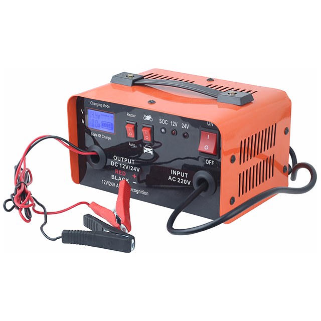
Proper sizing dictates operational success. You must match the nominal voltage of the charger exactly to the battery bank. A 24V bank requires a 24V output. Connecting a 48V unit to a 24V bank will destroy the batteries instantly. You should size the amperage output to roughly 10% to 20% of the battery’s total Ah (Amp-hour) rating.
For example, a 200Ah battery bank pairs well with a 20A to 40A unit. Rapid charging with higher amps seems efficient but generates excess internal heat. This heat accelerates battery degradation. Slower charging extends the overall lifecycle of the cells. Lithium batteries can often accept higher charge rates (up to 50% or 1C), but you must verify the maximum acceptance rate with the cell manufacturer before sizing the equipment.
Basic smart units use standard three-stage profiles. Advanced diagnostic units utilize up to seven distinct stages. These advanced profiles include soft-start, battery testing, and reconditioning phases. A soft-start phase gently introduces current to deeply depleted cells, preventing thermal shock. A reconditioning phase stratifies the electrolyte in flooded batteries, mixing the acid evenly to prevent stratification.
You must assess whether the premium for a seven-stage unit fits your specific operational use case. Deep-cycle marine applications and heavy equipment fleets benefit greatly from reconditioning. Standby backup systems usually operate fine with a high-quality three-stage profile.
Battery chemistry reacts differently based on ambient temperature. Cold batteries require higher charging voltages to overcome increased internal resistance. Hot batteries require lower voltages to prevent overcharging and thermal damage. Advanced units use external temperature probes that bolt directly to the battery posts. They monitor the physical temperature of the lead or lithium cells.
The microprocessor adjusts the charging voltage dynamically based on this data. This temperature compensation feature remains mandatory for industrial, outdoor, or high-load applications. Ignoring thermal management guarantees premature battery failure in fluctuating climates. Pushing standard voltage into a hot battery boils the electrolyte rapidly.
Modern power equipment integrates Bluetooth, Wi-Fi, and CAN bus communication protocols. Cloud-based data logging allows technicians to monitor charge cycles remotely. They can track energy input, peak voltages, and error codes from a central dashboard. This connectivity proves essential for large-scale fleet management.
It enables predictive maintenance strategies. You can identify a failing battery bank before it causes operational downtime by analyzing the historical charge data. If a specific forklift battery consistently requires longer absorption phases, the telematics system flags it for maintenance before it fails mid-shift.
Ingress Protection (IP) ratings dictate a unit's resistance against dust and water intrusion. High IP ratings serve as essential criteria for marine, RV, and heavy industrial environments. Exposed internal components fail quickly when subjected to harsh elements. Conformal coating on internal circuit boards prevents corrosion from salt air and high humidity.
IP Rating | Dust Protection Level | Water Protection Level | Ideal Application Environment |
|---|---|---|---|
IP20 | Protects against large objects | No water protection | Clean, climate-controlled indoor facilities |
IP65 | Completely dust-tight | Protects against low-pressure water jets | Covered outdoor areas, dusty warehouses |
IP67 | Completely dust-tight | Protects against temporary submersion | Marine decks, exposed heavy equipment |
Industrial high-frequency units utilize advanced switching technologies. They are designed for heavy-duty forklifts, fleet vehicles, and telecom backups. They offer exceptional energy efficiency and high scalability. They operate at high switching frequencies, which reduces the physical size of internal transformers. They carry a higher upfront cost but deliver superior energy conversion. They also feature detailed data logging capabilities for compliance tracking and fleet management.
On-board units integrate directly into vehicles or mobile equipment. Manufacturers pot the internal components in epoxy to withstand high vibration and mobile environments. They offer plug-and-play convenience wherever an AC outlet exists. However, they add physical weight to the vehicle. Off-board stationary units sit on workbenches or mount to facility walls. They allow for centralized, high-output fleet charging. They deliver higher amperage without burdening the mobile equipment with extra weight.
Maintainers are low-amperage devices built specifically for seasonal storage and standby generators. They output between 1A and 5A. They excel at preventing natural self-discharge over long periods of inactivity. They monitor the voltage and only supply current when it drops below a specific threshold. However, they remain entirely incapable of recovering deeply discharged high-capacity banks. Using a maintainer to charge a dead 100Ah battery will take days and may trigger internal safety timeouts.
Universal units feature user-selectable profiles for Lead-Acid, AGM, Gel, and Lithium chemistries. They provide high flexibility for facilities managing mixed-fleet environments. A single unit can service multiple equipment types. However, this flexibility introduces the risk of human error. If an operator selects the lead-acid profile for a lithium battery, the unit will apply the wrong voltage parameters. This error can damage the BMS or ruin the cells. Facilities using universal units must implement strict training protocols.
Mismatched equipment creates severe safety hazards. Applying excessive voltage to lead-acid batteries causes the electrolyte to boil off, releasing explosive hydrogen gas. A single spark in a poorly ventilated battery room can ignite this gas. Applying improper profiles to lithium batteries forces them into thermal runaway. Thermal runaway is an unstoppable chain reaction of heat generation that leads to fire.
Necessary safety features include reverse polarity protection, short-circuit protection, and spark-proof clamps. Solid-state relays inside the unit prevent sparks even if the clamps touch each other while plugged in. The unit will not output current until it detects a proper, safe connection to the battery terminals.
A smart unit might reject a completely dead battery. Microprocessors require a minimum voltage threshold to detect the battery's presence. If a 12V battery drops below 3V, the unit assumes no battery is connected. It initiates a safety lockout to prevent sending current into a short circuit.
Technicians can safely bypass this lockout using specialized supply or force modes. These modes push a low, steady current to raise the voltage enough for the microprocessor to recognize the battery and begin a normal cycle. You must monitor the battery closely during this recovery phase to ensure it does not overheat.
Regulatory marks remain non-negotiable for commercial procurement. You must verify that the equipment carries proper certifications. These marks guarantee the unit has passed rigorous independent testing for electrical safety and electromagnetic interference. Uncertified equipment introduces severe liability into your facility. If an uncertified unit causes a fire, insurance providers will likely deny the claim. Always request compliance documentation before finalizing any equipment deployment.
Certification Mark | Testing Focus | Relevance to Procurement |
|---|---|---|
UL (Underwriters Laboratories) | Electrical safety and fire prevention | Mandatory for North American facilities |
CE (Conformité Européenne) | Health, safety, and environmental protection | Mandatory for European operations |
FCC (Federal Communications Commission) | Electromagnetic interference limits | Ensures the unit won't disrupt other electronics |
RoHS | Restriction of hazardous substances | Ensures environmentally safe manufacturing |
A battery charger functions as a chemistry-specific power management tool. It remains critical to the longevity and safety of your power assets. Selecting the correct equipment requires matching the charging profile, amperage output, and thermal management capabilities directly to your battery fleet. Generic power supplies cannot replicate the precision of microprocessor-controlled units. Protect your infrastructure by deploying equipment engineered for your specific operational environment.
Take the following actions to ensure optimal equipment selection:
Audit your current battery inventory to identify exact chemistries and total Amp-hour capacities.
Consult your battery manufacturer's specification sheet to verify exact charging parameters and BMS compatibility requirements.
Evaluate your facility's environmental conditions to determine the necessary IP rating and thermal management features.
Verify all required safety certifications and compliance marks before requesting quotes from vendors.
Implement a standardized charging protocol to prevent operators from mismatching equipment with incompatible battery banks.
A: No. Lead-acid units often utilize desulfation pulses and continuous float charging phases. Lithium batteries cannot tolerate float charging or high-voltage pulses. Applying these profiles to lithium cells causes lithium plating, permanently damages the internal chemistry, and creates a severe risk of thermal runaway.
A: A smart unit utilizes integrated microprocessors to monitor the battery's state-of-charge continuously. It communicates with the internal Battery Management System (BMS) and adjusts the voltage and current output dynamically based on real-time feedback, internal resistance, and ambient temperature.
A: Smart units feature safety lockouts requiring a minimum voltage threshold to detect a connection. If a battery is deeply discharged below this threshold, the unit assumes a fault or short circuit. You must use a specialized supply or force mode to recover it.
A: Size the amperage output to roughly 10% to 20% of the battery's total Amp-hour (Ah) capacity. A 100Ah battery requires a 10A to 20A unit. Lithium batteries generally accept higher charge rates, but you must always verify the maximum acceptance rate with the manufacturer.
A: Applying a higher nominal voltage forces excessive current into the cells. This causes severe over-voltage, rapid outgassing, physical swelling, and permanent internal damage. It poses a significant risk of explosion or fire. You must always match the nominal voltages exactly.
A: A trickle charger supplies a continuous, low-amperage current regardless of the battery's state, which can cause overcharging over time. A float charger monitors the voltage and only supplies current when the voltage drops, safely maintaining a full charge without damage.
A: Temperature shares an inverse relationship with required charging voltage. Cold environments increase internal resistance, requiring higher voltage to push current. Hot environments require lower voltage to prevent overcharging. Temperature compensation features automatically adjust this output to prevent damage.
